Hard Drive Motor Wiring Diagram
Wiring diagrams, sometimes called " main " or " construction " diagrams, show the actual connection points for the wires to the components and terminals of the controller. Wiring diagrams m c w bulletin 600 bulletin 600 manual starting switches are designed for starting and protecting small ac and dc motors rated at 1 hp or less where undervoltage protection is not needed.
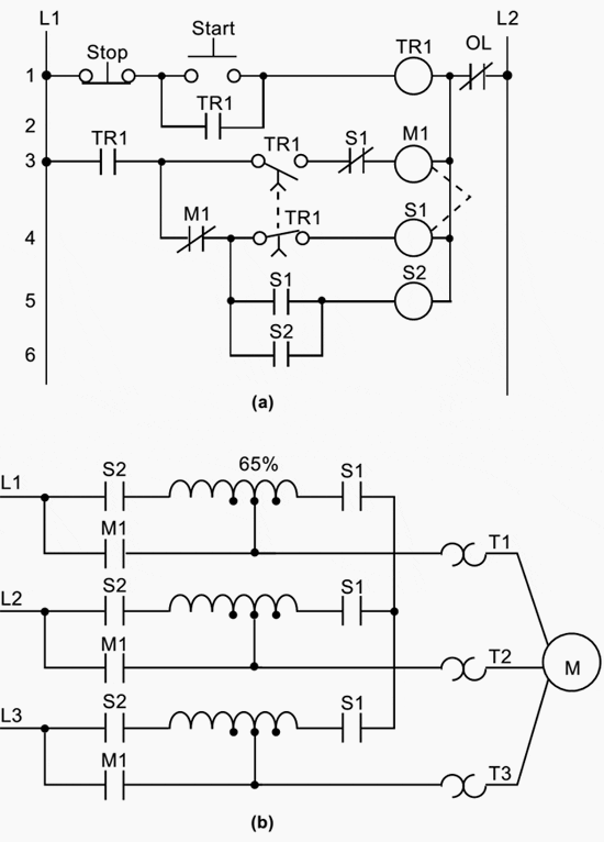
PLC application for reduced voltagestart motor control
To stop the actuator we set both pins to low (see line 21 and 22 in code below)and to reverse the direction of motion we.

Hard drive motor wiring diagram. Hard disk motor requires 3 shifted pulses to run.you can get information about the stepper motor and running machanism in some other article of instructible. Inst maint & wiring_5.qxd 20/11/2015 11:37 am page 7 Manent magnet rotor and wire wound stator poles.
The drv8313 does not include sensor inputs. Hdds are accessed over one of a number of bus types, including as of parallel ata (pata, also called ide or eide; The red and black wires of the 30a speed controller are connected with the lipo battery pack.
The common wire of the hard disk brushless dc motor is not connected. The chip can supply up to 3.5 a from an 8 to 60 v supply. Luv 5v 12v brushless dc motor driver controller board for hard drive 3 4 wire fc sho singapore.
Single & three phase blower connection diagrams, * thermally protected Dc 12v 36v 15a 500w brushless motor controller hall. The hard disk motor 3 wires are connected with the 30a speed controller.
Does anyone have a wiring diagram for a pro drive 36 or know where i can find one. 5v 12v dc brushless motor driver 3 4 wire makerfabs. I just want to make the motor spin.
N s a c a a b b c c b com com com n n s s 110 010 011 101 100 001 n s s n 6 3 4 1 2 5 a c b c b a com brushless dc motor control made easy. I am not using this for a computer. Simplified bldc motor diagrams author:
Up to 20% cash back the motor is known as a three phase brushless motor that is somewhat similar to a stepper motor which is another type of motor fond in hard drives. They can be used as a guide when wiring the controller. 5v 12v dc brushless motor driver 3 4 wire makerfabs.
One might ask why the twist was needed. Wiring schematic for pro drive. Wiring diagrams do not show the
It has reverse voltage protection, over current protection to ensure user safety. What you do is set the common of the hard drive motor to + vdd and that gives you 3 wire. A hard disk drive (hdd), hard disk, hard drive or fixed disk is a data storage device used for storing and retrieving digital information using one or more rigid (hard) rapidly rotating disks (platters) coated with magnetic material.
That you hook to y1 y2 y3 set the bridge en pin to low and switch a1 a2 a3 on and off in a row the motor will spin i used a i think 10ms delay to start the motor then after it was spining the code changed the delay to 5ms. Single voltage, wye connected, with partial current transformer protection: I managed to get the three wires by the handle messed up two are for the clutch and one plugs in to the motor all are black except one is purple with red stripe.
If it has its drive select jumpers set so that it is an a: They are operated by a toggle lever mounted on the front of the switch. Omc cobra wiring diagram chrysler striper service manual, wiring diagram omc motor wiring diagram wiring diagram for an omc ignition switch us motor wirind diagram cat 34ca2jh9.
Mon aug 15, 2011 5:33 pm. Single voltage, wye connected, with partial current transformer protection, lightning arrestors & surge capacitors: It is powered usually by a 4 wire plug (the connections from hard drive to the rest of the computer circuit.
Thu aug 25, 2011 2:53 am. Since the signals are inverted, the drive after the twist responds to commands backwards from the way it should; Ward brown microchip technology inc.
By setting one of these pins low and the other high (see line 18 and 19 in code below) we can extend the actuator at maximum speed. Hard disk motor interfacing with arduino, circuit diagram: The motor driver is connected to two pwm digital pins (pins 10 and 11 on the arduino uno).
Airflow airflow airflow airflow * * these diagrams are current at the time of publication, check the wiring diagram supplied with the motor. First let's start with the circuit diagram. Device, it responds to b:
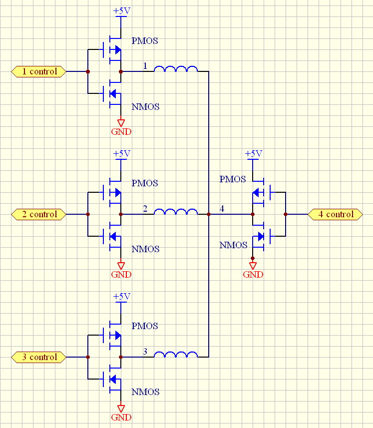
Hard Drive Stepper Motor with high speed spinup circuit — Parallax Forums

Wiring Diagram For Internal Hard Drive
Wiring Diagram For Internal Hard Drive
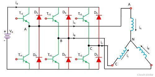
What is Brushless DC Motor Drive? Definition & Types Circuit Globe

(Howto) Walz a Hard Drive Spindle Motor Tutorials Community

Wiring Diagram For Internal Hard Drive
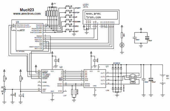
Stepper Motor Driver Ic L297 Schematic lasopamall

5V12V DC Brushless Motor Driver Board Controller For Hard drive motor 3/4 wire Wire, Motors
hard drive stepper motor driver Electronics Forum (Circuits, Projects and Microcontrollers)
Post Edited (Beau Schwabe (Parallax)) 2/13/2010 115630 PM GMT
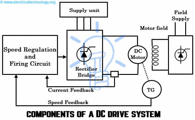
Wiring Diagram Hard Drive Motor 12

Toshiba Motor Wiring Diagram Complete Wiring Schemas
Post Edited (Beau Schwabe (Parallax)) 2/14/2010 24356 PM GMT
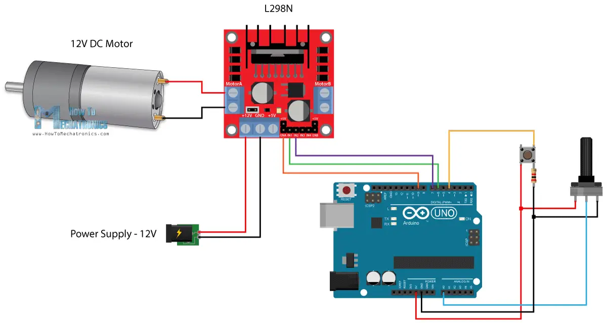
Wiring Diagram Hard Drive Motor 12

I have an old hard drive 3 phase brushless motor (3 wires) that I want to power via DC battery

Hard drive motor circuits Circuit, Induction heating, Hard drive

31 Brushless Motor Wiring Diagram Wire Diagram Source Information
Wiring Diagram For Internal Hard Drive

Wiring Diagram Hard Drive Motor schematic and wiring diagram

